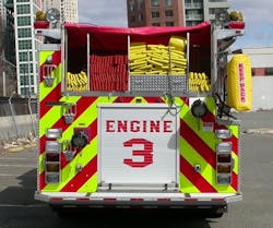
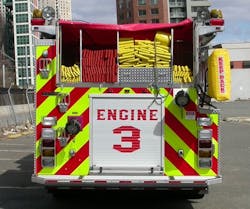
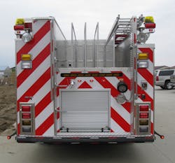
The size and amount of hose to be carried on a fire apparatus has an effect on the design of the rig. Recommended minimum hoseloads for fire apparatus that are equipped with a fire pump are spelled out in NFPA 1901: Standard for Automotive Fire Apparatus, but fire departments often choose to carry more hose than is recommended for a variety of reasons. Fire departments must evaluate their hose needs carefully and adjust their specifications to ensure that the new fire apparatus is capable of carrying out its mission.
A hosebed, or hose storage, is available in a variety of arrangements on today’s fire apparatus, starting at the front bumper with a trash line, to an arrangement of crosslays/speedlays, and ending at the back of the apparatus with the main hosebed.
It is important to realize that the decision-making process in the design and specification of fire apparatus is very much like a game of dominoes in that every decision that’s made affects other items and/or functions on the apparatus.
If a department moves to 1,000 feet of 5-inch supply hose from 600 feet of 4-inch supply hose, the effect on hosebed size is significant. If this department wants to carry the same current complement of firefighting hose with this addition of supply hose, the length and/or height of the vehicle might change significantly.
Rear hosebed
Probably the single biggest rear hosebed request is that it be conveniently low, so firefighters can safely work off of the back of the vehicle. Some departments specify a measurement from the ground or the backstep surface to the floor of the hosebed that can’t be exceeded. The size and shape of the booster tank and the body style/dimensions are the two factors that have the biggest influence on hosebed height.
In regard to storage space: 500 gallons of water takes up approximately 67 cubic feet. Consequently, as the capacity of the water tank is increased, valuable hose storage space is reduced, thus raising the hosebed height.
Modified rescue body pumpers that have lower side compartments (approximately 24 inches deep on both sides of the body) and high side compartments (approximately 12 inches deep on one side and approximately 24 inches on the other side) reduce the space that’s available in the rear hosebed (Figure 2). This also narrows the space that’s available for the booster tank. Rescue body pumpers that have approximately 24-inch-deep compartments on both sides of the body can increase significantly the height of the hosebed floor (Figure 3). The rescue body configuration along with the specified amount of on-board water affect the hosebed height and hose capacity and raise the center of gravity. Once the full-depth (approximately 24-inch) compartments are added above the chassis rails, the compartment body then occupies the space that the traditional T-shaped booster tank normally occupies, thus displacing water. As a result, the booster tank must be reconfigured to maintain the department-specified water capacity, which often means that the hosebed floor must be raised.
Changing the configuration of the booster tank can help to lower the hosebed. This can be accomplished by making the booster tank L-shaped. When this is done, the front portion of the tank is raised, and the rear portion is lowered. The end result is a lower hosebed floor height but a possible loss of midship dunnage storage. Additionally, the length of the hosebed is reduced, which translates into a higher stack of hose. Although you might achieve a lower hosebed floor height, the hose stack is higher, which might make it difficult to deploy the hose and unsafe to reload. The only solution to lower the hose stack might end up being to increase the length of the vehicle, so the hosebed is longer.
Other options that can influence the rear hosebed height include rear intake, rear discharge, inboard ground ladder storage, and sleeved storage for ground ladders, hard suctions and long-handle tools. All of these cause alterations to the booster tank, which displaces water volume. Consequently, to maintain the specified water capacity, the tank configuration must be altered, which translates into pushing the hosebed floor height up or increasing the length of the vehicle to achieve a lower tank height.
The ultimate question becomes, “How does one achieve a lower hosebed floor height, so firefighters safely can work off of the rear of the vehicle?” The answer is driven by firehouse limitations, response district limitations and compartment configurations. The options are limited to:
Lengthening the compartment body of the apparatus, which raises the following questions:
- Will it fit in your firehouse?
- Does your response district support maneuvering a longer truck through the district, or do you have narrow streets, parking on both sides or other physical limitations that won’t allow this?
Reducing water-tank capacity raises the following questions:
- Is the fire district well-hydranted to the point where the capacity of the water tank can be reduced?
- If yes, do you really need to be hauling around 750 or 1,000 gallons of water?
Modification to body style/configuration, which raises the following questions:
- Is there a need for rescue-style, high-side compartments? (A careful analysis of the equipment to be carried should be completed to determine whether traditional highside compartments are adequate, which in turn allows for the water tank to have a wider profile, thus keeping it lower in the body. This will be best reviewed with the body and plumbing engineers during a preconstruction conference.)
- Can the department utilize an L-shaped water tank? (Be mindful of the previously discussed issues that arise using this configuration: shorter hosebed length, which creates a higher stack and higher center of gravity.)
Successfully specifying and receiving a workably low rear hosebed can be difficult to accomplish because of all of the variables that are involved. To prevent specifying the impossible, work with the manufacturer’s representatives to ensure that what is specified is doable. Finally, use the manufacturer’s engineers during the preconstruction conference to confirm or modify what is specified to improve upon what is trying to be accomplished.
Once the hosebed design is confirmed, some other simple no- or low-cost items can be specified to make the hosebeds more user-friendly. Keep in mind that it isn’t necessary to have the hosebed dividers be the full height of the hosebed. Specify that the hosebed divider height be ±10 inches higher than the specified hoseload, which makes repacking the hose much easier. Looking at Figures 3 and 4, one will see single-stack 1¾-inch and 2½-inch hose bays. It should be pointed out that 2½-inch, single-stack hose is difficult to pack, and 1¾-inch hose is next to impossible to pack, particularly using pistol grip nozzles, because they don’t fit in a single-stack bed. If possible, use a minimum of double-stack hose bays in the rear hosebed, crosslays or speedlays.
Hand holds near the top of hosebed dividers should be specified to allow firefighters something to grab for increased safety while working the hosebeds.
Crosslays
Most fire apparatus that are equipped with a fire pump now are specified to include a hosebed that allows for hose to be transversely stored across the width of the vehicle, which allows for hoselines to be deployed from either side of the vehicle. These can be configured in what is sometimes referred to as a “dry load” hoseload or a “wet load” hoseload (preconnects). Most frequently, these hosebeds are located on top of the pump module or on the front of the body adjacent to the fire pump. Because these hosebeds are designed to carry firefighting handlines, the challenge is keeping the hosebeds low enough to the ground for the firefighter to reach the nozzle when deploying the handlines. Specifications must include the amount of hose to be carried in these hosebeds. Working with a manufacturer’s representatives ensures that the impossible isn’t being specified.
Commonly arranged in one, two or three hose bays, a variety of hoseloads are carried here. Most often, configurations are two 1¾-inch crosslay preconnects and one 2½-inch crosslay, which usually is a dry bed but occasionally preconnected.
Preconnected hoselines often are equipped with a Chiksan swivel, so they can be deployed from either side of the vehicle. When more than one crosslay with the same diameter hose is specified, they usually are packed with one nozzle to each side of the vehicle. Some preconnected hoselines are connected directly to discharge gates on the pump panel rather than Chiksan swivels.
Regardless of the hose diameter, specify hosebed dividers to be a minimum double stack for ease of packing. Also, the dividers that are between the crosslays can be specified to have the outside edges notched about 5–6 inches down from the top and about 10–12 inches in from the edge, which will help with bulky nozzle storage.
Speedlays
Speedlays are low-mounted crosslays that are placed below the pump operator’s panel on a top-mounted pump or at the leading edge of the pump enclosure on a side-mounted pump. Operationally, there is little difference between the speedlay and the crosslay, but, because of their low mounting height, speedlays deploy quickly and easily.
On top-mounted pumps, speedlays generally are located on the front of the pump enclosure in the walkway and are equipped with a removable panel, cargo net or vinyl hosebed cover, which makes repacking fairly easy. With a side-mounted pump module or on a top-mounted pump module, packing can be difficult because of the lack of access. Chiksan swivels usually are mounted in the top of the speedlay alcove, favoring one side of the apparatus, and the hose is packed in a removeable tray with some slack on input end. Removable trays are removed from the vehicle for loading the hose. The tray then is lifted and slides into the alcove, and the hose is attached to the Chiksan swivel. This allows for loading the hose on the ground. These most frequently are manufactured out of aluminum or polypropylene. Consider ordering an extra tray for each hoseload, so they can be loaded with hose and ready to be placed on the vehicle.
When specifying hose trays, be sure to stipulate four hand-hold cutouts in the speedlay trays about 14–16 inches back from the outboard edges, which will help with lifting loaded trays into the vehicle. Also, some departments allow for space on the apparatus and purchase a narrow folding table that is stowed on the vehicle, so members can pack the trays standing up instead of kneeling on the ground.
Other considerations
When specifying hosebeds, make sure to identify the flooring material that is desired.
Consider specifying a solid surface under the hosebed flooring on the crosslays to keep exhaust heat from the pump module from damaging the hose over time.
Carefully examine the need for hose rollers adjacent to the crosslays and speedlays. Couplings that come out of the hosebed can damage the side of the vehicle or get caught on obstructions that might exist on the side of the vehicle.
Departments tend to want to carry more equipment than the vehicle that’s being replaced carries. This causes apparatus size to increase. Departments must evaluate these needs and desires and review their current hoseloads to see whether they can be modified to keep the vehicle’s operational efficiency at its optimum.
About the author
Jeffrey Gaskin retired as a 36-year member of the Scarsdale, NY, Fire Department with more than 30 years of fire apparatus purchasing and consulting experience. He is an EVT-certified apparatus mechanic. You can contact him at [email protected].
Greg Stone retired as a 33-year member of the Los Angeles Fire Department with more than 20 years of fire apparatus purchasing and consulting experience. You can contact him at [email protected].
About the Author

Jeffrey D. Gaskin
Jeffrey D. Gaskin is president of Big Red Trucks Fire Apparatus Consultants. He is a retired captain from the Scarsdale, NY, Fire Department. Throughout his career, Gaskin has been involved in apparatus acquisitions, from needs assessment through specification-writing. He also is a fire apparatus mechanic and holds certifications from Allison Transmission, Detroit Diesel, Hale Pump, Smart Power, Spartan Chassis, Sutphen Fire Apparatus and others. Gaskin is certified by the Emergency Vehicle Technician Certification Commission in six areas: Fire Apparatus Inspection, Maintenance and Testing (F-1); Design and Performance Standards of Fire Apparatus (F-2); Fire Pumps and Accessories (F-3); Aerial Fire Apparatus (F-5); Allison Automatic Transmission (F-6); and Hydraulic Systems (F-8). He can be reached at [email protected].

Greg Stone
Greg Stone is a retired 33-year veteran of the Los Angeles Fire Department. His assignments with the department included apparatus and equipment purchasing responsibilities. Additionally, Stone has 25 years of apparatus purchasing experience assisting other departments with their purchasing needs.
