Apparatus Supplement: Step Surface Safety
You’ve probably all heard the word “ergonomics,” which is an applied science concerned with designing and arranging people and things so that they interact in the safest and most efficient manner. There are actually many areas of fire apparatus engineering and design that embrace ergonomics, including the following examples:
· Dashboard instrumentation, controls and activation from the driver’s seat position
· Location of handrails, steps and illumination around the perimeter of the vehicle
· Height of hosebeds
· Attack line placement and deployment
· Mounting provisions for tools and equipment within the body compartments
· Aerial ladder pedestal controls and illumination
Many of these areas, and others, are addressed within NFPA 1901: Standard for Automotive Fire Apparatus, which serves as a good starting point when developing vehicle specifications. Specifically, Section 15.7.1.1 states, “The maximum stepping height shall not exceed 18 inches with the exception of the ground to first step, which shall not exceed 24 inches when the vehicle is loaded to its estimated in-service weight.” Other sections of the standard address the minimum step surface depth, slip resistance, and the minimum slip resistance for exterior walking surfaces.
New within the 2016 edition of the NFPA 1901 Standard is a requirement to designate walking and standing surfaces higher than 48 inches from the ground that are not guarded by a railing. With the increased number of apparatus with upper-body compartments and walkways that are unprotected, Section 15.7.1.6 was adopted to enable apparatus manufacturers to clearly identify acceptable walking surfaces on the apparatus.
According to NFPA firefighter studies, 39.2 percent of all reported injuries occur on the fireground, with over 45 percent of these injuries involving sprains, strains and falls. Additionally, 21 percent of all injuries were caused by falls and slips. While the fire service has made great progress of integrating safety into all aspects of our daily operations and training, this area continues to be problematic for our personnel. With this in mind, let’s review two common examples of how operating on or around our apparatus fleet can present safety concerns—bumpers and step configurations.
Bumper extensions
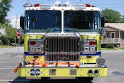
A local department was conducting an after-accident report (AAR) involving a member who slipped off the front bumper extension on Engine 1 while cleaning the windshield, resulting in a twisted ankle and some lost time from work.
When the department’s apparatus committee was conducting a pre-bid meeting for their next new vehicle, the committee requested a pair of horizontal handrails at the front of the cab, below the windshield, so personnel would utilize these handrails rather than grab onto the windshield wiper arms when climbing onto the front of the apparatus. The responses from the vendors were quite different.
One prospective bidder stated that this was a standard option for their custom cabs and could be provided at a nominal cost. A second manufacturer responded that cab cowl handrails could not be provided, as they did not consider the front bumper area to be a standing or stepping surface. Despite the use of NFPA 1901-compliant non-slip aluminum treadplate for this surface, they would not provide the handrails, as their engineering department indicated that the handrail locations would not be compliant with the NFPA Standard. The suggested alternative was for the department to clean the windshield from the ground or utilize a step ladder. Apparently, no one from this manufacturer had ever attempted to clean a windshield on one of their vehicles after returning from a run during the wintertime when the upswept portion was dirty from road dirt and deicing chemicals.
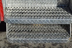
Another fire department that operated where snow and ice conditions were prevalent requested that all cab and body step surfaces be provided with an aggressive non-slip insert, and provided several images of acceptable types of material. When reviewing and evaluating the three bid proposals, two manufacturers supplied the requested non-slip inserts without a problem. The third bidder noted compliance but supplied its standard aluminum tread plate and claimed that this met the intent of the NFPA 1901 Standard. The cost difference between the standard aluminum treadplate and what the department requested for all of the stepping surfaces around the vehicle amounted to just under $2,500. It did not come as much of a surprise that bidder three left out several other requested components in an effort to be the lowest bid price. Why is this important? Because specifying something that exceeds the minimum requirements of NFPA 1901 is based upon the Authority Having Jurisdiction (AHJ) experience and desire to enhance the safety and operational capabilities of their apparatus fleets.
Look at the front of your apparatus. When designing a new custom chassis vehicle, make sure that the front bumper is provided with a full-width steel reinforcement channel that is supported back to the chassis frame extension. This will reduce the chance of cab intrusion in the event of a frontal collision. Also carefully review the angle of approach to ensure that the amount of bumper extension, and anything hanging below, does not impede the ability of the apparatus to transition from a level surface to any change in road elevation.
If you are in doubt as to what angle of approach would work, particularly if the bumper extension is considerably longer than any vehicle in your fleet, have the municipality’s engineer determine the road bed grade and provide this to the manufacturer to verify that the apparatus will perform as required. This also applies to rear body overhangs, particularly on mid-mount and rear-mount towers that are longer than any other comparable aerial devices.
Step configurations
Over the past several years, we have taken the opportunity to attend the National Truck Equipment Association’s Work Truck Conference, where various classroom-style sessions cover fleet management, maintenance practices as well as chassis manufacturer product updates. Much like major fire shows, the exhibit floor provides an opportunity to meet with component vendors and interact with other fleet managers.
This past year, it was interesting to note that several manufacturers of Class 7 and 8 commercial chassis placed emphasis on driver’s comfort and enhancements, including dashboard layouts, position of mirrors and window controls, depth of cab steps and step heights, along with airbags and other safety equipment. Granted that drivers of these vehicles spend most of their work day behind the wheel when compared to an engine chauffer or technician in a busy station.
The commercial truck industry places a high degree of engineering effort on interior creature comforts, windshield viability and component access for maintenance. Due to the greater numbers of Class 7 and 8 heavy truck chassis that are built each year, when compared to the fire apparatus, the commercial truck segment receives a lot more feedback on vehicle design and reliability, which have been emphasized over the past several years. Examples of this effort can be seen in the dashboard layouts where panels are located so the driver can easily reach switch and upfitter controls without losing eyesight of the road.
During the most recent conference, we reviewed several dozen heavy commercial truck chassis to assess various cab step configurations and could not find one where aluminum treadplate was utilized for step surfaces. The heavy truck industry is clearly far ahead of the fire service with respect to different types of aggressive, non-slip surfaces that prevent mud, snow and ice from accumulating on the horizontal surface.
Cab entrance steps should be a primary area of concern where, depending upon your local weather conditions, the standard horizontal piece of aluminum treadplate with embossed diamonds may not provide the safest step surface. While all manufacturers’ cabs will meet the intent of the NFPA 1901 step heights for the lower and upper surfaces, depending upon axle, spring and tire components, an auxiliary third step may be required. More than a few apparatus have been initially delivered with the standard configuration only to have personnel injured with subsequent modifications made to change the step and handrail locations.
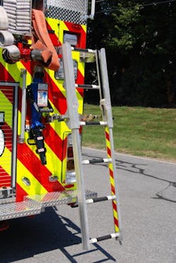
There are several additional considerations at the rear of the apparatus, including access to the hosebed and protection of body components, such as handrails and waterway inlets on aerial devices that may extend past the body rear vertical surface. Older pumpers were typically designed with beavertail panels that supported the rear step and provided a mounting surface for fixed corner steps to access the hosebed. With the move toward a flat-back, squared-off body on rescue engines and other vehicles, NFPA 1901-compliant folding steps and handrails are the preferred method for hosebed access. Even if these steps are positioned on 18-inch centers as required, try climbing up four or more of these in a row in street clothes and then assess if there might be a better way to safely climb up to the hosebed.
There are any number of apparatus currently in use, or ones that you might see on display at a fire show that, while they meet the intent of the minimum NFPA step height requirements, are unsafe for personnel due to lack of planning and attention to how your personnel will operate around these vehicles.
Where possible, design engine apparatus with low hosebeds using either an L-shaped water tank or longer body, or employing a short beavertail panel to permit at least a 16–18-inch rear step if the height of the hosebed will require personnel to stand on the rear step when deploying hoselines. If your department operates with a four-way hydrant valve or mounts other appliances on the rear tailboard, make sure that this equipment can be located within this area and not impede access to the hosebed, ground ladders or other equipment.
On rescue engine and non-walk-in rescue bodies, an alternative may be to specify an access ladder that can be mounted to the left- or right-side rear body panels. There are several styles available, including those that fold up against the body and permit an easier angle for climbing, similar to a wall ground ladder. Any moving portion of these ladders should be tied into the vehicle door open circuit.
Everything counts
Operational safety for our personnel should be of paramount importance, with consideration given to all four sides of the apparatus, including the top of the body. Even if portions of the vehicle are not required to be inspected on a daily basis, at some point our personnel will be required to access these areas for maintenance and testing.
Do not overlook any aspect of the vehicle design that could reduce or eliminate the opportunity for an accident. A lot of fire trucks look great on paper but do not perform well in the field because we overlooked the little things. Everything counts so everyone goes home safe.

Tom Shand
TOM SHAND, who is a Firehouse contributing editor, is a 36-year veteran of the fire service. He works with Michael Wilbur at Emergency Vehicle Response, consulting on a variety of fire apparatus and fire department master-planning issues. Shand is a member of the Firehouse Hall of Fame.

Michael Wilbur
MICHAEL WILBUR, who is a Firehouse contributing editor, retired as a lieutenant in FDNY, where he was last assigned to Ladder Company 27 in the Bronx. He has served on FDNY's Apparatus Purchasing Committee and consults on a variety of apparatus-related issues around the country. Wilbur is a member of the Firehouse Hall of Fame. For further information, access his website at www.emergencyvehicleresponse.com.


