Apparatus Architect: Low, Short & Compact
The task of developing clear and concise technical specifications for fire apparatus often falls to a group of personnel within the fire department that have a diverse perspective on the mission of the vehicle. These perspectives are often based upon personal experience on other units and how well they performed based upon several characteristics. For the driver, it may be how the apparatus handles the streets within the response district. For the officer, it could be the amount of room in the seat area and access to radio and resource material. The fleet manager and maintenance personnel will consider vehicle downtime and aftermarket warranty support, while the firefighter would judge the ease of climbing in and out of the cab and accessibility of frequently utilized tools and equipment.
It may appear as an impossible task, but the goal of developing apparatus specifications is to acquire a vehicle that not only meets the needs of the department, but also provides an optimum total value, including initial purchase cost, life cycle maintenance costs, fuel and insurance costs. Today’s apparatus are more complex due to engine emissions and electronic components that have a direct impact on vehicle performance and downtime. Well-written and developed specifications ultimately help determine replacement cycles for front-line apparatus, which, in turn, can drive the requirements for the financial resources required to adequately fund the replacement program.
Apparatus innovations can be found in all areas of a vehicle, and sometimes it is the small, seemingly minor enhancements that make all the difference between a unit that is universally praised by all users versus an apparatus that has no supporters. The late Chief Alan Brunacini was credited with the statement, “Any firefighter can outperform all of the safety aspects we have in a nanosecond.” Taking this quotation a step further, a lot of fire truck designs look great on the paper from a safety perspective, but when the apparatus is assigned out to a station, any number of persistent issues arise, causing the crew to lose confidence in the vehicle.
Common sense, yet innovative design
One of the first design concepts for any vehicle should be to meet the intended mission of the apparatus, taking into consideration the hazards in the response area, staffing and training levels for your personnel and the desired tools and equipment to be carried. No matter how hard we try, you cannot make up for lack of staffing with acquiring oversized, multi-function apparatus that in some cases are overweight and require frequent warranty and maintenance work, resulting in extensive downtime.
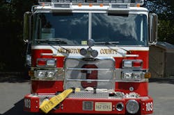
Starting at the front bumper area, here are a few concepts to consider when designing your next engine apparatus. Front intakes are useful to assist the engine chauffer to secure a water supply. When equipped with a swivel, this permits the apparatus to achieve a position that does not block access for incoming units and allows for increased flexibility. In most cases, the use of a swivel elbow for the front suction piping requires a longer bumper extension, which impacts the angle of approach and may limit the amount of cab tilt for unit maintenance. An alternative for the front suction intake is to have the 5-inch pipe terminate just below the cab and notch the front bumper for the intake hose, while still permitting the soft sleeve hose to be preconnected to the intake.
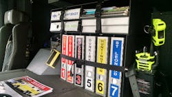
While many departments reply upon laptop, tablet and other GPS-enable devices for determining response routes, others make good use of map books that can provide additional information on building layouts and access, water supply and other details. Provisions for carrying multiple map books inside of the cab for each response district can provide valuable information for the crew. When combined with the jurisdiction’s standard operational guidelines (SOGs) for structural fires, the officer can establish where the apparatus should be positioned and points of access for the building.
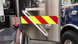
Safety should be paramount in any portion of the vehicle design, and this should start with a review of access to the cab and body compartments. All step surfaces should be provided with aggressive, non-slip surfaces, and depending upon your local weather conditions, may require more than the standard raised diamond, aluminum tread plate. The position and location of handrails should be determined, including areas inside of the cab, to enable personnel to maintain three points of contact at all times.
When evaluating interior compartment space on the body, consideration should be given to reviewing the frequency of use for all appliances and tools that are going to be carried on the vehicle. In some areas, it is necessary to carry an assortment of adapters due to different hose and hydrant threads. Equipment that is utilized frequently on most incidents should be mounted within the body and again clearly marked to provide a description of the tool and to make it easy to identify a missing item when taking up from the scene.
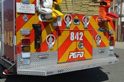
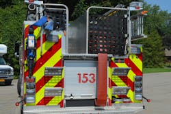
Water tank design has improved greatly over the past several years where L-shaped tanks can provide a lower rear hosebed for both supply and attack line deployment. The goal should be to design the hosebed height to permit personnel to stretch and advance any one of the attack lines without having to climb onto the rear step of the apparatus. At times, due to the amount of equipment that is required on the vehicle, full-depth body compartments may be needed on one or both sides of the apparatus. This rescue body design generally requires a rectangular water tank and increases the height of the hosebed floor. In these cases, care should be exercised to maintain a balance between the length of the body and height of the hosebed area without sacrificing operational safety and efficiency.
There are several methods to meet the intent of the NFPA 1901 Standard with respect to covering and securing the rear hosebed area. The use of aluminum hosebed covers has increased since the development of the traditional two-piece hinged design, which works well but generally requires personnel to climb on top of the cover to raise each side unless the covers are provided with electrically controlled cylinders. Constructed of 3/16-inch aluminum, the cover can be released from the rear step and slide toward the front of the hosebed with the fixed part of the cover then designed to raise up to permit access to the hosebed area.
Keys to success
Determining the appropriate chassis, pump and body components can seem like an overwhelming task when starting to develop new vehicle specifications. While keeping a focus on the safe and efficient operation of the vehicle, rely upon common sense solutions to provide an apparatus that will perform under all conditions and receive high marks from both line personnel and the fleet maintenance staff. Low, short and compact may be the keys to your success.
