Rural Firefighting Academy: The Rural Pressurized Fire Hydrant – What’s It Worth? Part 3
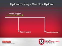
Before you begin flow testing, ask the water utility for a hydrant map that shows a diagram of the water-supply system. Reviewing the system layout lets the tester understand the underground water main sizing and flow direction. Understanding the direction of flow is important, as it lets you identify the location of test and flow hydrants. The water-supply system layout shown in Figure 4 has a dead-end hydrant. Note that the flow hydrant’s flow direction is located past the test hydrant.
When faced with a strong water supply system (high-gpm flow rate), it is sometimes necessary to open additional hydrants to achieve the minimum 10% pressure drop at the test hydrant. When opening multiple hydrants, all flow hydrants must be opened and tested at the same time, increasing the number of personnel and test equipment required. For example, Figure 5 shows a test hydrant on a loop system with up to two flow hydrants.
To prepare the test hydrant, use a hydrant wrench to ensure that the large-diameter and one 2½-inch outlet caps are tight and secure. Remove the other 2½-inch cap, and then install and tighten the test kit cap with a pressure gauge. Open the hydrant fully, and then open the test cap bleeder valve and purge all of the air from the hydrant barrel. Close the bleeder valve and note the static pressure on the gauge.
One easy, cost-effective way to determine delivery rate from a flow hydrant is to use a test kit with prepared flow tables. We will use the Pollard flow test kit, which includes a fixed flow orifice and flow tables. The stream shaper shown in Figure 6 is a 2¼-inch inside diameter fixed discharge opening. Printed on it is a table that correlates pitot pressure to gpm flow.
To prepare the flow hydrant for testing, use a hydrant wrench to ensure that the large diameter and one 2½-inch outlet caps are tight and secure. Remove the other 2½-inch cap and install the stream straightener from the test kit. With personnel positioned at the test and flow hydrants, fully open the flow hydrant. Edge the pitot blade into the center of the water stream on the flow hydrant and note the gauge reading. At the same time, note the residual gauge pressure at the test hydrant.
To obtain an accurate flow reading, you must hold the pitot over the discharge opening correctly – the end of the blade centered in the water stream. Hold the blade a distance equal to half the pipe’s diameter away from the end of the outlet, as shown in Figures 7A and 7B. The tester positions his left hand on the discharge opening and edges the blade into the water stream to the correct position. Record static and residual pressures at the test hydrant and the pitot gauge flow pressure at the flow hydrant.
After obtaining the pitot gauge reading, slowly close the flow hydrant to prevent water hammer. Remove the stream straightener. Close the test hydrant and remove the test cap and gauge. After checking for proper barrel drainage, secure all hydrant caps. Note and report any hydrant defects.
Graphing test results
Back at the firehouse, it is time to graph the hydrant flow-test results. The results of our testing showed a test hydrant with a static of 85 psi and a residual of 62 psi. The flow hydrant produced a pitot gauge flow pressure of 46 psi. According to the test kit’s pitot pressure/flow table, a 46 psi pitot gauge reading equals 902 gpm.
Using the graph form found in SOP 612, we can plot the data and prepare a water supply curve for the test hydrant. The hydrant water supply curve is valuable in pre-fire planning because it shows what we can expect from a fire flow standpoint when we use the test hydrant during a fire emergency. For example, according to this curve, we now know that the test hydrant is capable of providing up to 1,550 gpm at a residual pressure of 20 psi; see Figure 8.
Using the Iowa State Rate of Flow or the National Fire Academy’s Needed Fire Flow formula to calculate the amount of water required for target hazards in the testing area, we can intelligently plan water supply. If structures in the area of a hydrant test require fire flows higher than 1,550 gpm, we will need to identify an additional water source.
We hope you have found these columns on testing pressurized hydrants helpful. For more information, the Rural Firefighting Academy offers a Pressurized Hydrant Analysis Online Course at LiveFireTraining.com. The course includes a model Standard Operating Procedure on testing pressurized hydrants. Students who successfully complete the four-hour course receive a certificate of completion from the academy to document their achievement.
REFERENCES
• National Fire Protection Association 291, Recommended Practice for Fire Flow Testing and Marking of Hydrants, 2013 ed.
• American Water Works Association M17: Installation, Field Testing and Maintenance of Fire Hydrants
• Wieder, Michael, Fire Service Hydraulics and Water Supply, 2nd ed.
DOMINIC COLLETTI is the chief training officer at the Rural Firefighting Academy. The academy provides online self-paced learning programs for the small community firefighter using leading fire service instructors. He can be reached at LiveFireTraining.com. This month’s column is an excerpt from the Rural Firefighting Academy’s Pressurized Hydrant Analysis online course. Part one was in the February issue and part two was in the March issue.
About the Author
Dominic Colletti
DOMINIC COLLETTI is the chief training officer at the Rural Firefighting Academy. The academy provides online self-paced learning programs for the small community firefighter using leading fire service instructors. He can be reached at LiveFireTraining.com. This month’s column is an excerpt from the Rural Firefighting Academy’s Rural Firefighting Operations Online Course.
