Standpipe systems can be found in occupancies that range from apartments to high-rises to large commercial buildings. These systems are relatively simple, yet most of the breadth of knowledge that most firefighters possess doesn’t extend past the standpipe outlet. Members must have a general understanding of how the system operates to ensure proper function and to troubleshoot any issues that might arise. Fires in standpipe-equipped buildings can be challenging enough but are compounded greatly when the system malfunctions.
This article focuses on automatic wet systems equipped with a fire pump. This includes combination sprinkler/standpipe systems.
An automatic wet system is filled with water and capable of supplying an attack hoseline from a standpipe outlet at pressures that are based on NFPA 14: Standard for the Installation of Standpipe and Hose Systems and the era of the building.
Although some of the items that are discussed below are specific to automatic wet systems, many of them apply to other types of systems.
Domestic supply & FDC
The automatic wet system receives its baseline static pressure from a domestic water supply source. The water supply comes in on the suction side of the fire pump and is controlled by the supply control valve. This is the main water shutoff for the entire system. In some installations that lack a fire pump, the domestic water pressure is what members have available at the standpipe outlet factoring for friction loss and elevation.
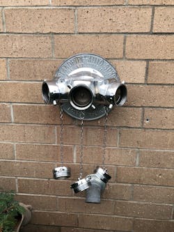
On the exterior of standpipe-equipped buildings is one or more fire department connections (FDC). The FDC allows the department to supply the system via department apparatus should the fire pump fail or a pressure that’s higher than what the pump is producing is required.The FDC often is supplied by more than one inlet, such as a siamese or trimese. Some authorities having jurisdiction (AHJ) allow for the FDC to be a large-diameter-hose (LDH) connection, although this isn’t recommended, because required pump pressures for large buildings often exceed the operating pressure of standard LDH.
It’s important to understand that the FDC doesn’t augment the pressure that’s generated by the building’s fire pump. Either the fire pump or the FDC is supplying the system. This occurs as the FDC is located on the discharge side of the fire pump and is equipped with a one-way check valve. The check valve doesn’t permit water to enter from the FDC unless the pressure that’s generated by the fire pump is exceeded. Once the fire pump’s pressure is exceeded, water from the FDC is allowed to enter, and the check valve occludes the water that comes from the fire pump.
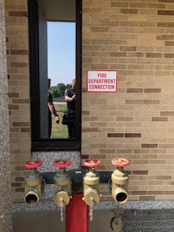
Also located on the exterior of a fire pump-equipped building is the test header. The test header is designed to facilitate water discharge during the annual fire pump test that’s performed by a fire protection company or the AHJ. The test header consists of male threads—and sometimes gate valves, which often are located on an exterior wall very near to the pump room. (In high-crime and urban environments, these appliances can be removed and capped to prevent theft.) The threaded connections allow the testing company or agency to connect hoselines that can be run safely to sewer drains or other discharge locations.Like the FDC, the test header is located on the discharge side of the fire pump. Unlike the FDC, the test header has a manual valve that must be opened to allow for its use. During normal operating conditions, members encounter the valve in the closed position. However, if water is coming from the test header on arrival, a member must be sent to the pump room to ensure that the valve is closed. Although very rare, the test header can be used as a last resort to supply a system with a missing or damaged FDC when pressure-reducing valves are on lower floor standpipe outlets.
Jockey pump & fire pump
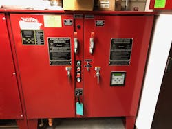
The heart of the system is the fire pump. Many components permit the fire pump to work as designed: the jockey pump, the jockey pump controller, the fire pump, the fire pump controller and, in some installations, a transfer switch.
The brains of the operation are the controllers. They sense a drop in pressure/water flow and signal the appropriate pump to run.The controllers are located in cabinets that are near to the designated pump. Power switches for the controller/pump—knife or rotary switch, depending on the controller—are on the exterior of the cabinets. The switches should be in the “on” position during normal operation. During an incident, a member should be sent to verify that the switch is in the “on” position and that the pump is running. If the pump isn't running, members can attempt to manually start it by pressing the "Start" button that's on the front of the controller.
In addition to the power switch and "Start" and "Stop" buttons, an emergency run switch is on the exterior of the fire pump controller. The directions for use vary, but clear instructions should be located on the cabinet immediately adjacent to the switch.
The emergency run switch bypasses the automatic functions of the fire pump controller and signals the fire pump to run. The emergency run switch should be used in cases where the pump didn’t kick on despite water flowing from the standpipe system and the manual "Start" button fails to operate the pump.
Some systems also are equipped with a transfer switch. It routes power from a secondary power supply—often a standby emergency generator—should the primary power system fail. The transfer switch is designed to operate automatically should the primary power supply fail.
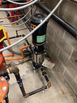
Two types of pumps are located in these installations: the jockey pump and the main fire pump. The jockey pump maintains the system pressure to just shy of the flow from a single sprinkler head activation. It accounts for any fluctuation in domestic water pressure and minor leaks that are in the system.
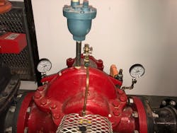
When the system detects a pressure drop/water flow that exceeds the set limit, the fire pump controller signals the fire pump to run. When the fire pump is engaged, it provides the maximum preset pressure, as calculated by the fire protection engineer, to ensure sufficient outlet pressures at the most remote outlet as designated in NFPA 14.To ensure the proper function of the fire pump during a standpipe operation, a member should be sent to the pump room to examine two pressure gauges that are located on either side of the pump. The gauge that’s located on the suction side of the pump reads the domestic water pressure. The gauge that’s located on the discharge side of the pump reads the pump discharge pressure. When the fire pump isn’t running, the gauges should match.
When the fire pump goes into operation, the gauge that’s on the discharge side of the pump provides the pressures that are generated by the pump. This gives members an idea of what pressures they can expect at the standpipe outlets once friction loss and elevation are factored in. This gauge also can give members an idea of what pressure must be exceeded while supplying the FDC to overtake the fire pump.
Risers, etc.
Risers, control valves and drains vary greatly depending on the installation.
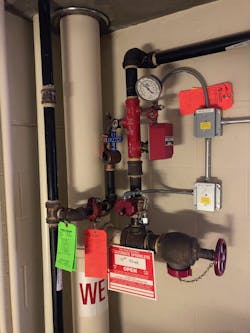
In general, the piping that comes out of the discharge side of the pump branches into one or more risers. The risers carry water to various locations in the building for the standpipe and sprinkler systems. Often, the risers can be isolated using individual control valves. If members encounter a standpipe outlet on an automatic wet system that’s either dry or has no water pressure, a member must be dispatched immediately to identify and open any riser valves that are in the closed position. These valves should be equipped with electronic tamper switches that are tied to the alarm system—although they only trigger a local supervisory trouble alarm, which often isn’t investigated.In some installations, zone control valves are attached to the standpipe risers. In such an installation, the fire protection sprinklers receive water from the standpipe riser. The zone control valves allow for isolation of the fire protection sprinklers that are assigned to a specific zone, often an entire floor.
Several types of drains are found in these systems. The most common one is the main drain, which usually is located in the pump room. The entire system is drained by the main drain, which leaves the fire protection system without water. An individual riser drain drains the water from the isolated riser.
Riser drains can be found in various locations in a building, depending on where the system grids to that specific riser.
Zone drains allow the fire protection system that’s assigned to a specific zone to be drained without draining the entire riser or system.
Dedicate the time
Members should be able to troubleshoot basic issues that might arise during an incident that requires the use of a standpipe system. This knowledge doesn’t come without practice.
Fires in standpipe-equipped buildings can be challenging enough when the system is functioning as designed, let alone when there’s an issue with the system. It’s critical that engine companies get out and walk-through the various pump rooms that are in their district.
About the Author

Jonathan Hall
Jonathan Hall, who is a Firehouse contributing editor, has more than 24 years of fire service experience. He currently is a captain with the St. Paul, MN, Fire Department assigned to Engine Company 14. Hall also serves as a lead instructor in the department's Training Division; he teaches hands-on skills to members of all ranks. Hall is the co-owner of Make The Move Training LLC and teaches engine company operations throughout the country.
