In the world of rope rescue, we use mechanical advantage systems really for two reasons. The first being a force increasing tool and the second, a means of reducing the weight of a load during a lowering operation.
Mechanical advantage systems (MAS) are broken down into three categories:
- Simple MAS
- Compound MAS
- Complex MAS
Although the three types of systems will provide the same outcome, each is unique in assembly and force calculations. Allow me to explain.
First, we have the simple mechanical advantage system. In a simple system, all of the moving pulleys in the system move towards the anchor at the same rate of speed. Below are two examples of simple pulley systems (see Figures 1 and 2.)
Physics tells us that anytime we add a system to another system on the input or hauling side we multiply those numbers to get the new MA. If I had a 2:1 MAS and then added a 2:1 MAS on the input side I would then have a 4:1 MAS.
Now, we'll look at compound mechanical advantage systems. The compound mechanical advantage is the result of adding one simple system to another on the input side. The same example we just used regarding the 4:1 MAS can be used here.
The last type of MAS, we will explore is called a complex mechanical advantage system. Complex MAS are simply done by combining a compound and a simple system. The example, shown in Figure 3, shows a 3:1 MAS being pulled by a 2:1 MAS resulting in a 6:1 MAS. When all is said and done, simple MAS have a greater stroke than compound or complex MAS of the same rating.
Theoretical Mechanical Advantage
When reading textbooks or learning about MAS in a classroom setting, the force and load calculations are considered the ideal mechanical advantage. In reality, what we are actually working with is called the theoretical mechanical advantage (TMA).
It's theoretical because every time a bend is created in the rope or the rope passes through a pulley, a percentage of the overall power of the system is lost. A good rule of thumb is a 10 percent loss for every pulley the rope passes through and two to three percent loss for a bend created in the rope.
Use pulleys in your system that are at approximately three times the size of the rope's diameter. This will ensure the least amount of strength loss by the rope passing through the pulley. When all is said and done, what you're working with is referred to as the actual mechanical advantage (AMA). Without special tools, such as a dynometer, you won't be able to figure out the AMA. As long as you have a pretty good idea of what your TMA is, it's safe to say you're in good shape.
Creating a Mechanical Advantage System
How does a mechanical advantage system work? Well it's pretty simple. Let's take a 2:1 MAS. It's comprised of an anchor, rope, pulley and carabiner (see Figure 4). The pulley attached to the load is called a traveling pulley. This pulley creates your mechanical advantage. However, for it to work the other end of the system must be anchored. If you have a pulley attached to a non-moveable object, it is referred to as an anchored pulley. It serves only one purpose: a change of direction.
As you introduce force into the system (pulling), that force is focused on the traveling pulley. If the load the pulley is attached to weighs 100 pounds, the 2:1 MAS now makes that same load 50 pounds (2 ???? 100 pounds = 50 pounds). To break this down further each side of the pulley will see half the load, 50 pounds on one side 50 pounds on the other thus creating the 2:1 MAS.
The first of the two numbers signifies the mechanical advantage (for example: 3:1). It also tells you that for every three feet of rope we move the load will only move one foot. Now, here is a bit of information for you that will be of use later down the road when calculating the MAS you will need. A rescuer can pull with a force load of 50 pounds so one rescuer utilizing a 4:1 MAs can pull a 200 pound load with relative ease.
Because of the load force, we generate (50 pounds) and in turn the pulling force a MAS creates there is something called the "Rule Of 18" that we must adhere to. Basically, it's a guide limiting the amount of rescuers used to pull on a haul system. Here's how it works. Let's take a 4:1 MAS. We'll take the amount of rescuers used and multiply that number by the first number in the MAS 4:1. If we have four rescuers we would multiply 4X4 which equals 16. Sixteen is under 18 so we are in good shape. If one more rescuer were added to the team, we would exceed our rule of 18 (5X4=20).
Here is an example of why we conform to the "Rule Of 18." Your rescue team is performing the rescue of a victim located in the bottom of a storage tank. You've rigged all the necessary rigging, secured a bombproof overhead anchor and have assembled nine of your strongest rescuers to perform the raising operation. The MAS you chose to use was a prepackaged 4:1 and the victim weighs approximately 250 pounds. The 4:1 MAS will now take that load and through the magic of physics make it 62.5 pounds. To make this load move we will have to generate a minimum pulling or input force of 62.5 pounds Now remember when I explained that a human on average can generate a pulling force of 50 pounds -- well this 62.5 pound load should easily be moved by two rescuers being their total input or pulling force is at least 100 pounds.
Here is where you will understand why we have the "Rule Of 18." We have nine rescuers ready to haul this load and nine rescuers multiplied by 50 pounds of input force each will generate a input or pulling force of 450 pounds. If any of the victim's limbs or packaging equipment should become caught on an obstruction during the hauling process, there is a good chance the team above won't feel that resistance and the end result would be minor or severe injuries to the victim and/or gear damage with possible failure.
Taking this example into account, during your size-up you will need to calculate the MAS needed based on the victim or "load" amount and the amount of personnel on scene. Standards dictate that when hauling a victim or "human load," because of the force generated by a 5:1 MAS is the maximum MAS that can be used. During this size-up you also need to take into account the amount of rope you will need to use to build your system. Let's look at an example. A 4:1 MAS that is 30 feet above a victim will need at least 120 feet of rope to create the system plus additional rope to reach the area you will be hauling from. Like every rescue operation proper planning and a solid skill base is are a necessity.
Progress Capture Device
Now, let's look at another component of a MAS. It's called a progress capture device (PCD). The job of a progress capture device is to hold the load when you need to reset the haul system as well as catch the load in the event the rescuers lose contact with the rope. This in no way replaces the independent belay system you will need to construct. Let's take a second and talk about the job of the PCD. If you built a 4:1 MAS that measured 20 feet in length from pulley to pulley, the stroke of that system is probably about 18.5 feet because you must subtract for the knot and size of the pulleys being used.
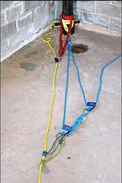
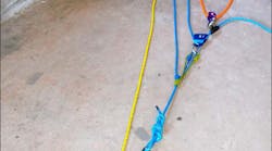
Once the system reaches its maximum stroke, it's time for the PCD to do its job. In the example (see Figure 5), twin triple wrapped prusiks are used. These prusiks will be locked allowing us to reset the system or "stretch" it out to its original size or stroke. Something I must cover is the positioning of the tandem prusiks. If the prusiks are positioned improperly, they will not do their job. Let's briefly talk about how a prusik hitch works.
If you look again at Figure 5, you will see a prusik hitch applied to a main line. The friction caused by the rapid sudden movement of the main line will cause the prusiks to move forward and lock. The triple wrap of the prusik hitch causes a torsional pressure on the rope thus causing the main line to stop forward movement. Proper placement in the system is vital. The prusik hitch should be on the load side of the system. What that means is the rope that is connected to the load. If you're unsure of the placement, give the system a short haul and look at the movement of the ropes. On most systems the last rope moving towards the load when the system is released is going to be your target rope. Systems such as a 4:1 for example will have a slightly different placement of the prusiks simply because of system reset needs.
Mechanical advantage systems can have many applications in your rescue operations. You don't always need pulleys and carabiners to create them either. A simple example would be the lowering of a stokes basket down a set of narrow or steep stairs. Find yourself an anchor. That anchor can even be your partner. Run the rope down and through the head of the stokes and back up to you. You've just created a simple 2:1 mechanical advantage that can aid you in either lowering or raising the patient in the stairwell.
In Closing
Mechanical advantage systems allow us to move heavy loads with relative ease and control. All you need is the training to bring it all together. Next month we will cover how to calculate the mechanical advantage by simply looking at the system. We'll also cover anchor and belay systems and the rolls they play in a mechanical advantage system.
Until then stay safe and stay progressive.
MICHAEL R. DONAHUE is a 13-year veteran of the fire service is assigned to Rescue Company 1 in Elizabeth, NJ. Mike is the owner and founder of Progressive Rescue, a company dedicated to further firefighter's in all aspect of the job. He holds the title of rescue specialist with New Jersey's Urban Search and Rescue Team (NJ-TF1) and he is actively teaching at Middlesex and Somerset fire academies and the Middlesex County College as their Fire Science Program Coordinator. Michael has been guest on two Firehouse.com podcasts: The Buzz on Technical Rescue: Special Operations Roundtable and The Buzz on Technical Rescue: Rope Rescue Operations. View all of Michael's artices and podcasts here. You can reach Michael by e-mail at [email protected].

Michael Donahue
Owner and founder of Progressive Rescue, Mike Donahue is a 13-year veteran to the fire service. In those thirteen years Mike has experience as both a volunteer and federal firefighter and has been a career firefighter in the City of Elizabeth for the last 10 years, the last seven of which and currently working out of Rescue Company 1. Mike holds the title of Rescue Specialist with New Jersey's urban search and rescue team (NJ-TF1). You can find Mike actively teaching at Middlesex and Somerset Fire Academies as well as Middlesex County College as an Adjunct Professor and the Fire Science Program coordinator. He is actively involved in writing new course programs for the various organizations he teaches for. Mike has reviewed several text books for publishers such as Delmar and Jones & Bartlett. Mike has also co-written the new rope program for Jones & Bartlett and taught Rope Rescue Made Simple at Firehouse Expo 2010. Mike also is a monthly columnist for Firehouse.com covering the area of technical rescue. His teaching techniques and cutting edge style have gained the respect from many of his peers. Mike's passion, experience and desire to educate emergency service providers prove to be the driving force that has made him so successful. Progressive Rescue prides itself on providing the most cutting edge, diverse instructional programs available. We strive to provide your department with the most comprehensive, dynamic learning experience available at a truly competitive price. You can reach Mike by e-mail at [email protected]


