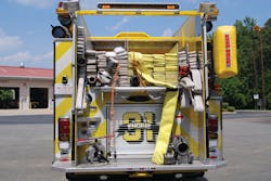
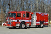
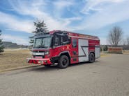
Since our last installment of the Apparatus Architect covered the importance of carrying the appropriate complement of ground ladders on aerial apparatus, we believe equal time should be devoted to having a discussion on hose loads on engine companies. Much like the quint aerial has gained acceptance for truck company service, many departments have acquired multi-purpose rescue engine units in an effort to carry additional tools and equipment. Unfortunately, in an effort to package the necessary equipment, hydraulic rescue tools, ground ladders and hand tools results in a much higher hosebed than was initially anticipated. Some fire departments go to final inspection and do not even recognize their own truck.
A fire department recently placed into service a new pumper equipped with a 1,000-gallon water tank that was designed to carry the normal complement of engine company tools. During the design process, the apparatus committee decided to specify an L-shaped water tank with the thought that this could lower the height from the ground to the bottom of the hosebed, making hoseline advances safer and easier to accomplish. Many apparatus manufacturers do not detail or specify this dimension on their blueprints, so fire departments may be surprised when they measure the hosebed height during the final inspection to learn that the combination of features that they asked for resulted in a less-than-satisfactory arrangement.
A number of large departments, including Atlanta, District of Columbia, Milwaukee and New York City, have employed bulk-style water tanks, which resulted in the hosebed being down at the level of the chassis frame rails. With a 500-gallon water tank, this enabled personnel to back stretch from the apparatus while safely standing on the rear step. While the National Fire Protection Association (NFPA) 1901 Standard for Automotive Fire Apparatus permits the use of folding steps and other devices to access the hosebed area, some body configurations can result in difficult maneuvers to gain access to the hosebed areas and can become a safety concern.
For this reason, some departments have favored the use of crosslay or speedlay hosebeds for pre-connected attack lines. Depending on the space required for pump-panel controls and equipment storage above the fire pump, this configuration may provide an alternative to having all of the required attack lines loaded in the rear of the apparatus. Careful consideration must be made to ensure that these hosebeds are located no more than 64 to 66 inches from the ground and can be easily repacked when pulled. On many custom-chassis apparatus, the combination of the diesel-particulate filter and other exhaust-system components can impact the running board step surfaces on the right side of the vehicle. Additionally, engine companies whose apparatus are equipped with multiple transverse hosebeds must continually train to leave sufficient space in front of the structure to allow adequate room to position the aerial apparatus.
Planning for hosebed functionality
When developing specifications for transverse hosebeds, details should be provided to call out the required clear height and width of each hosebed and the type of nozzle that will be used on the attack line. Some departments have been dismayed when they determine that their nozzles with pistol-grip-style handles do not fit into the available space. The type of crosslay cover and netting on the exterior of the hosebed can also impact how you may load your hose and the steps needed to rapidly deploy these lines. While a minor point in the overall construction of the apparatus, these areas should be covered in detail during the engineering conference with the manufacturer prior to construction of the apparatus.
Moving around to the rear of the apparatus is where there are many options for ground ladder, hard-suction hose and long tool storage. All of these impact the shape and height of the water tank, which ultimately impacts the hosebed area. At one time, the standard water tank configuration was T-shaped with some portion of the tank located over the center rear-step compartment. Over the years, as more departments desired to carry electric reels and hydraulic rescue tools, options were created to have higher and deeper rear compartments that would accommodate a variety of these tools. The result was the water tank became shorter and the hosebed floor was higher from the ground.
The next evolution of body design came with the development of poly water tanks that could easily be made in any configuration to accommodate ground ladders enclosed within the body or the tank itself. Rear-body compartments for hard-suction hose, pike poles and other tools all require space, which impacts the working height in the rear hosebed. So while many of these options seem plausible, in an effort to enclose all of your equipment, in the end the hosebed height suffers and now you will require additional body steps to access these areas.
You may have heard the expression “no two water tanks are alike” from the apparatus salesperson due to the innumerable options that drive booster-tank configurations. The L-shaped water tank, which can provide for a lower hosebed height, works well with 500- to 750-gallon tanks. Larger-capacity tanks, because of overflow requirements and the height of the upper portion of the tank, often do not provide the same results as the smaller tanks. An often-heard complaint about the L-shaped water tank is that when all of the supply line is loaded, the top of the layout hose is about as the same height as you have on your current rigs. Most manufacturers, once they are provided with the details of the type of hose and dimensions, can calculate where the top of the actual hose load will be within each hosebed.
Departments that operate with having all of their attack lines loaded in the rear will require multiple 2½-inch or larger discharges for each line in order to avoid having to rely on a gated wye or water thief. Doing so makes sense; however, each of these discharges will require a separate sleeve through the water tank, which impacts the height of the water tank. We hear stories of firefighters who were injured when climbing onto an apparatus or who slipped and fell off the step area during an incident. It is one thing to get everything that you want on the apparatus and have it built by someone, but it’s another to have done your homework and be assured that what you are asking to be built is safe and will enhance and improve your engine operations on every call.
Safety around hosebeds
When developing specifications for new pumpers, take the time to measure your existing apparatus, which can be used as a point of reference for any discussions. The height from the ground as well as the width and length of each bed should be determined, which can then be used to confirm that the configuration of the new apparatus hosebed area will work out. This effort should be made before signing the contract with the manufacturer with all of the critical dimensions called out, including the height from the ground to the bottom of the hosebed once the vehicle is fully loaded. Perhaps you should ask that these dimensions are noted on your blueprint.
The stepping surfaces and associated handrail locations then may be determined based on actual use rather than relying on a standard placement for these components. Where possible, fixed steps or access ladders should be specified for access to the top of hosebed to rack hose and for maintenance. When properly designed, any attack line or leader line should be located so that personnel can stretch and advance the line without having to climb onto the apparatus using fold-down or auxiliary steps. The rear step, where possible, should be at least 14 inches deep, provided with an aggressive non-slip surface and made at least as wide as the hosebed.
The hosebed area on any engine apparatus is the real working end of the unit and careful consideration should be made to design safety and efficiency into this often overlooked area. We often hear the expression “It didn’t look that big on the drawing” from departments during the initial phase of a final inspection. As brother Tom always says, “Every fire truck ever built fit on a piece of paper.” Paying attention to the small details when laying out the hosebed configuration will pay big dividends when you place the new engine into service.
TOM SHAND, a Firehouse® contributing editor, is a 37-year veteran of the fire service and works with Michael Wilbur at Emergency Vehicle Response, consulting on a variety of fire apparatus and fire department master-planning issues. MICHAEL WILBUR, a Firehouse® contributing editor, recently retired as a lieutenant in the New York City Fire Department, where he was last assigned to Ladder Company 27 in the Bronx. He has served on the FDNY Apparatus Purchasing Committee and consults on a variety of apparatus-related issues around the country. For further information, access his website at www.emergencyvehicleresponse.com.


