Engine Essentials: Achieving Defensive Fire Flows With Dual Supply Lines
Obtaining a positive water supply often is considered a mundane assignment on the fireground. For smaller fires in residential and commercial occupancies, the task doesn’t require much thought. However, as the size of the fire increases or as water supply issues are encountered, suddenly, this regularly simple task becomes immensely important. Complicating factors include distances to hydrants, hydrant flow capabilities, maximum hose pressures, required fire flows and relay operations. Engine companies must be prepared to rapidly and effectively complete water supply operations at more complex incidents.
Fireground flows
For most residential fires, fire flows aren’t much above that of a 1¾-inch attack and backup line—approximately 300–370 gpm total. In reality, this flow range is well within what can be supplied by a single 2½-inch hoseline. That said, it still is advisable to utilize a larger supply line, in case the fire escalates and increased flows are required.
- Jonathan Hall will present “Engine Company Operations at Apartment Fires” at Firehouse Expo 2023.
For most commercial fires, fire flows typically are about that of a 2½-inch attack and backup line or a portable ground monitor—500–600 gpm total. This gets into a flow range that requires 3-inch or large-diameter hose (LDH) supply lines. As fire loads and the sizes of the structures increase, strong consideration must be given to establishing a water supply, or multiple supplies, that can accommodate a sudden need for high fire flows.
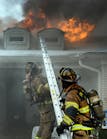
As fires grow and require defensive strategies to be utilized, fire flows dramatically increase. It isn’t uncommon for flows to reach or exceed 1,500–2,000 gpm. A relatively “routine” defensive fire often includes multiple 2½-inch handlines, portable monitors, deck guns and even aerial master streams. These operations often require that multiple water supplies be established in hopes of keeping up with the required fire flow.
Hydrant spacing
Hydrant spacing is set by the authority having jurisdiction and usually is based on NFPA 1: Fire Code and/or American Water Works Association standards. NFPA 1
states that for one- and two-family dwellings “the maximum distance to a fire hydrant from the closest point on the building shall not exceed 600 ft.” NFPA 1 further states that “the maximum distance between fire hydrants shall not exceed 800 ft.” This means, in the worst-case scenario, the nearest hydrant would be 600 feet away from the dwelling, and the next closest hydrant would be 1,400 feet away.
For buildings other than detached one- and two-family dwellings, NFPA 1 states that “the maximum distance to a fire hydrant from the closest point on the building shall not exceed 400 ft” and “the maximum distance between fire hydrants shall not exceed 500 ft.” This gives engine companies a worst-case scenario of the nearest hydrant being 400 feet away from the building and the next closest hydrant being 900 feet away.
These longer distances to hydrants from buildings must be examined to help to predetermine a plan for larger/more complex incidents. Often in defensive fire situations, several hydrants are required to meet the fire flows and to supply various apparatus positions on the fireground. Engine companies must understand the hydraulics that are required to effectively supply fireground operations with increased fire flows and distances.Hydrant pressures
Hydrant pressures vary by jurisdiction and even geography within a jurisdiction. Commonly, static hydrant pressures range from 50–100 psi. The resulting residual pressures often are sufficient to supply the fire flows that are required at dwelling and small commercial fires through a single LDH supply line.
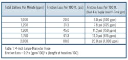
As such, many departments choose to utilize a forward lay approach using LDH. This is effective for smaller fire flows, but the concept can be detrimental during defensive operations or with longer distances to the hydrant. Without placing an engine on the hydrant to pump it, members rely on the residual pressure from the hydrant to supply the needed volume for the distance of the lay. As the volume and/or distances increase, so, too, does the friction loss in the LDH.Friction loss in LDH is reduced greatly compared with that of medium-diameter hose, and members often describe it as being negligible. This is true only for lower gpm fire flows. As an example, if we look at Table 1 (next page), we see that at 1,000 gpm, 100 feet of 4-inch LDH has a friction loss of 20 psi. If an engine company attempted to forward lay from a hydrant that has a residual pressure of 40 psi at 1,000 gpm, in theory, the farthest that the hydrant could push that volume of water passively through LDH is 200 feet.
Placing an engine at the hydrant allows the pressure to be increased and pushed a greater distance through the LDH—within the pressure specifications of the hose (see below). In addition, it allows the engine to take advantage of all of the hydrant discharges, thus maximizing the possible flow from the hydrant. Finally, it provides redundancy in the system in case the primary attack engine fails.
Heavy hookups
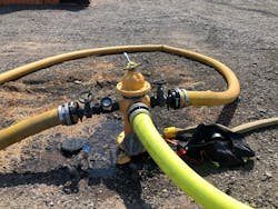
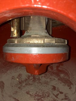
The goal of the engine pumping the hydrant should be to maximize all available water from the hydrant. This involves utilizing all of the usable hydrant discharges and connecting to them with LDH to minimize friction loss. If necessary, gate valves can be placed on outlets to facilitate a rapid initial water supply while still allowing for the system to quickly expand as time permits. Often, in the haste to rapidly establish a water supply, the hydrant itself isn’t fully opened, which creates a restriction and affects the available flow.
Members should have an understanding of their hydrant system and what it’s capable of supplying. Further, members should have access to hydrant maps and/or other resources that quickly allow them to identify hydrants and their rated flows. Members must understand that a hydrant that has a rated flow of 500 gpm won’t be capable of supplying 2,000 gpm.
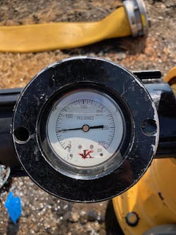
Hydrants often are rated with a residual pressure of 20 psi. NFPA 291: Recommended Practice for Water Flow Testing and Marking of Hydrants recommends that fire hydrants maintain a residual pressure of 20 psi for effective firefighting as well as to prevent backflow that could contaminate the public water supply. Many departments adopted this 20 psi residual pressure as policy and state that the engine’s intake pressure gauge shouldn’t drop below 20 psi when operating off of a hydrant supply.This 20 psi residual pressure recommendation is easy to follow with lower fire flows, but when engine companies attempt to maximize all of the available water, this potentially leaves a lot behind. It’s important to remember that this 20 psi residual pressure is designed to be measured at the water main. The fire department doesn’t have an effective way to measure water main pressure on scene and often relies on the residual pressure reading of the engine’s intake gauge, which takes the reading at the pump. There’s a lot of friction loss between the water main and the pump that isn’t accounted for utilizing the intake gauge: the barrel of the hydrant, fittings, supply hose, apparatus plumbing, etc. Placing a gauge on a hydrant discharge is the most accurate reading that’s available on the fireground, because it excludes the friction loss forward of the hydrant discharge.
Dual supply lines
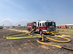
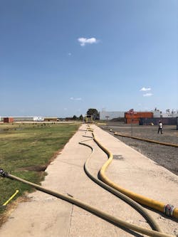
Dual supply lines involve running two LDH lines between the engine that’s pumping the hydrant and the primary attack engine. The need for this supply concept comes from the increased friction loss in LDH at higher flows as well as the maximum operating pressure of LDH. The recommended maximum operating pressure of rubber supply LDH often is cited as 185 psi; jacketed attack LDH is 275 psi. (Consult the manufacturer for exact specifications.)
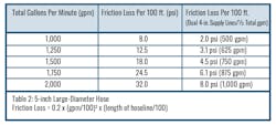
In Table 1, the friction loss of 100 feet of 4-inch LDH with a flow of 1,500 gpm is 45 psi. This means that the maximum distance between the engine at the hydrant and the primary attack engine that’s utilizing supply LDH is approximately 400 feet (45 psi x 4 100-foot sections = 180 psi). If the department has a policy that requires 20 psi residual pressure, the distance decreases by one section, assuming 100-foot lengths are used (300 feet). This could present an issue, given the hydrant spacing distances that were discussed above.Using dual 4-inch LDH lines with flows of 750 gpm each results in the same 1,500 gpm flow, but the friction loss is reduced to 11.3 psi per 100 feet of line. This means that the maximum distance between the engines is approximately 1,600 feet (11.3 psi x 16 100-foot lengths = 180.8 psi). Again, using a department that has a 20 psi residual intake pressure results in a total length of 1,500 feet using 100-foot sections.
Most engines aren’t equipped with multiple LDH discharges. Concerns often are expressed that a smaller discharge isn’t capable of supplying the higher flows. NFPA 1901: Standard for Automotive Fire Apparatus notes, “If piping and valving are sufficient, much higher flows for a given outlet might be achievable … A 3-in. valve can easily supply a 5-in. connection at 1,000 gpm, with little noticeable loss through the valve and the pipe.” Often, 2½-inch discharges are supplied by 3-inch valves and pipes. Check individual apparatus specifications and flow test each discharge.Put it into practice
Engine company members must be prepared to supply large volumes of water over protracted distances. Members must be familiar with their hydrant systems, hose and apparatus specifications, department policies and hydraulic calculations to determine the best course of action on the fireground. As always, members must train on these concepts and procedures to ensure that they can place them into operation rapidly and effectively.

Jonathan Hall
Jonathan Hall, who is a Firehouse contributing editor, has more than 24 years of fire service experience. He currently is a captain with the St. Paul, MN, Fire Department assigned to Engine Company 14. Hall also serves as a lead instructor in the department's Training Division; he teaches hands-on skills to members of all ranks. Hall is the co-owner of Make The Move Training LLC and teaches engine company operations throughout the country.
