Topic: Winching with a snatch block and components
Objective: Understand critical aspects of winching operations when using a snatch block tool in a rigging system
Task: The rescue team shall apply a snatch block tool in a rigging system, so the load on all components, including the snatch block, is maintained at or below their safe working load limit.
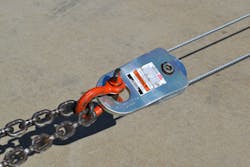
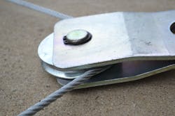
A snatch block is a simple tool. Although it actually is a class of lever, basically it is a wheel that has a grooved edge, called a sheave, or pulley, that’s mounted onto a unit that has sides that open to allow it to straddle the wire rope line of the winch. As the snatch block name implies, opening the side plates allows the block to be easily inserted anywhere along the length of the wire rope.
When rigged into a system, a snatch block can be arranged as a running block (also known as traveling block), where it physically moves as the pulling effort takes place (see Figure 1).
(Note: Although the examples that are pictured in this column demonstrate the use of steel wire rope, the same rigging concepts and principles apply if a rescue team is winching using synthetic rope.)
Therefore, with a running block system, the snatch block must be attached to something that moves as the pulling effort from the winch is applied.
Consider a disaster scene scenario where a heavy object must be moved horizontally using a winch rigging system to provide the pulling power. A running snatch block would be secured directly by strap or chain to the heavy object that must be moved. The wire rope line from the rescue truck’s winch travels out and goes around the pulley (sheave) of the snatch block, making a U-turn. The line then returns to an anchor point at the rescue truck near the winch. With this rigging, the return line runs parallel to the incoming line.
Rescuers should recognize this as a common and familiar rigging for a winch that results in the object—and the snatch block that’s attached to it—moving as the effort is applied from the winch. With this running block rigging and “two moving lines to the load,” there is a 2:1 mechanical advantage gained. All rescue personnel who have winches in their inventory should have the equipment that’s needed and be capable of setting up a 2:1 mechanical advantage as described. A wise rescuer however remains aware that despite having the two lines sharing the load, the snatch block itself will carry at least the full load of the pull. How to calculate this stress factor or angle factor is explained later in this article.
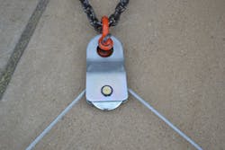
The same snatch block can be secured directly to an anchor, be it man-made or natural, making the snatch block into a fixed block (Figure 2). As the winch operates and the load moves, the fixed snatch block doesn’t move its location during the pulling effort. If the wire rope from the winch is run to the fixed block and then proceeds outward to the load or moveable object, the rigging results in a change of direction.The pulling effort comes from the winch as it travels through the pulley of the fixed block and out toward the load. There is no mechanical advantage to this fixed block, change-of-direction arrangement. Rescuers must determine the angle that’s between the incoming and outgoing lines, because this is the angle that factors into determining the total load on the fixed snatch block.
Snatch block D/d Ratio
Snatch blocks must be matched to the line that runs through them. The goal is to have the diameter of the winch line (steel or synthetic) be able to be properly supported as it goes over and around the pulley (sheave) of the snatch block. The formula is called the D/d Ratio. The “D” represents the diameter of the snatch block pulley. The “d” represents the diameter of the winch line. When they are compared, they yield a D/d ratio. To be most efficient, the D/d ratio should be greater than 20. Many snatch blocks have labels that inform the user with what diameter rope they are compatible, to maintain an acceptable D/d ratio.Snatch block WLL
Similar to chain and wire rope, a snatch block is rated by the manufacturer with a safe working load limit (WLL). This number usually is expressed in pounds of load, which shouldn’t be exceeded during the use of the snatch block. The process that a snatch block manufacturer would use to arrive at the published WLL for its block begins by placing the block under a load in a laboratory setting. In the laboratory, it is pulled or stressed until it fails. Multiple tests can be conducted until an average load at the point when the tool destructively fails, called its ultimate load or breaking strength, is determined. The manufacturer then calculates the WLL for its snatch block from this failure load, usually using a 4:1 ratio.
For example, if a snatch block has a published WLL of 8,000 lbs. and a design factor of 4, the tool manufacturer is telling us that the average breaking strength or ultimate load at failure during the laboratory testing was approximately 32,000 lbs. To work at or below the published WLL, the working load on the snatch block should remain below 8,000 lbs. throughout the task.It is critically important for rescue personnel to understand that they must mentally calculate and constantly monitor the estimated load that’s applied to the snatch block, so it remains at or below its published WLL. If this is maintained, responders have a relative safety factor of 4:1 in their favor.
This margin of safety accounts for tool damage or abuse, shock loads, deterioration and other real-world situations that could cause the snatch block to fail. Likewise, the WLLs for all components of the rigging setup (chains, hooks, shackles, wire rope, etc.) must be known, and it must be ensured that the WLLs for each of them aren’t exceeded as well.
Stress formula/angle factor
The physics of this invisible but always present loading is called the stress formula or the angle factor. It all has to do with the angle that’s between the incoming winch line compared to the line that’s departing the block.
When we had a running block and rigged a 2:1 mechanical advantage system with the line that was going to the snatch block then returning to the winch parallel to the line that was coming in—called a 0-degree angle—the tension on each line was reduced because the two lines equally share the load.
However, the load on the snatch block could be as much as two times the load or effort exerted. When used for change-of-direction, a fixed snatch block can be loaded or stressed even more than the pulling effort or load itself. Proper rigging mandates that the load on the snatch block does not exceed its WLL. If it does, that’s our fault.
To remember the stress factors or angle factors, it is permissible for rescuers to refer to a number chart they carry with them. The load factor or stress factor number is multiplied by the load on the pulling line to calculate the load on the snatch block.
There is an entire set of numbers to be remembered (a chart to have with you) that allows rescuers to estimate individual line loads. When the lines are parallel in a 2:1 mechanical advantage system (0 degrees), each line shares 50 percent of the total load.
As the angle that’s between winch lines increases, such as in a change-of-direction rigging, each individual line takes on greater percentages of the total load. Below is some suggested guidance for calculating individual line load:
- 30-degree angle = 52 percent of total load on each line
- 60-degree angle = 58 percent of total load on each line
- 90-degree angle = 70 percent of total load on each line
- 120-degree angle = 100 percent of total load on each line
Once you know the load that’s on an individual line, you can use that number to calculate the load that’s on the snatch block. For example, if we rigged a change-of-direction fixed snatch block with the incoming and outgoing lines at a 90-degree angle to each other, our chart says that each line will carry 100 percent of the load itself. There is no mechanical advantage with this particular rigging.
If we estimate the load to be 10,000 lbs., our first calculation shows us that each line is carrying 100 percent of that load, or 10,000 lbs. Now we take that number and calculate the angle factor or stress factor. Guidance for determining the load that’s on the snatch block includes:
- When the angle that’s between the lines is 0 degrees, such as with a 2:1 mechanical advantage rigging, multiply the load of either line by 2.00 to determine the load that’s on the snatch block component
- When the angle that’s between the lines is 45 degrees (a change-of-direction system), multiply the load that’s on one line by 1.84
- When the angle that’s between the lines is 60 degrees, multiply by 1.73
- When the angle that’s between the lines is 90 degrees, multiply by 1.41
- When the angle that’s between the lines is 120 degrees, multiply by 1.00
- When the angle that’s between the lines is greater than 120 degrees, the load that’s on the snatch block will be less than the load that’s on any individual line
If in our example scenario, the load that’s pulled is 10,000 lbs., we calculate that the angle factor is 1.41 because of the 90-degree angle that’s between the lines. This all figures out that the snatch block load is 14,100 lbs.
This estimated load might be beyond the WLL of your snatch block. Our rigging layout must avoid overloading the winch, snatch block and every single component that’s used. Overloading beyond the safe WLL or any physical damage to the block or components that are used can result in anything going wrong.
The danger zone
Your rigging layout must avoid overloading the winch, snatch block and every single component that’s used. Overloading beyond the safe WLL or any physical damage to the block or components that are used can result in something going wrong violently and instantly—and potentially lethally.
Failure might occur at the winch end, at the end that’s by the load or anywhere along the rigging layout itself. At the moment of failure, with the wire rope drawn tightly, the snatch block itself (which might weigh anywhere from 15–50 lbs.) can create a flying missile that travels at great speed through your rescue scene. Experience has shown that at the instant of failure, the wire rope and any broken or failed components most likely fly forward or rearward, particularly traveling in line with the winch line itself.Rescue teams should have weighted line dampener devices that can be placed on the line at several points. The added weight of commercially available or even improvised line dampeners that are placed over the winch line is intended to minimize the reaction of a failed rigging system, although dampeners aren’t designed to prevent the failure in the first place. To maintain a clear danger zone, a safety officer who is on scene must keep crewmembers and others away from the object that’s moved, the winch line, the winch unit and the snatch block, as well as anywhere along or near the wire rope. The winch operator—with a hard-wired remote control or, better yet, a wireless remote control—should be shielded from the winch line rigging during the pulling effort.
A common recommendation heard many times, refers to keeping a clear distance away from the rigging equal to 1.5 times the layout length of the rigging itself. If your winch rigging system were to ever fail, distance away from the rigging can save your life. If you live to hear the bang and wonder what just happened, you have survived the event. It is just that fast and results can be catastrophic.
Winching Snatch Block Skills
- Rig for a minimum 2:1 mechanical advantage operation
- Rig for a change-of-direction operation
- State WLL of all components within a rigging system
- Estimate loads on all components within a rigging system

Ron Moore
RON MOORE, who is a Firehouse contributing editor, recently retired as a division chief with the McKinney, TX, Fire Department and now serves with Prosper, TX, Fire Rescue. He self-published the Vehicle Rescue 1-2-3 training manual and serves as the forum moderator for the extrication section of Firehouse.com . Moore can be contacted directly at [email protected].


